title Image for Rehab Engineer main page
RTS Information (password required)
Link to my list of bookmarks
Link to Section 508 Information
Link to Case Study Index
Link to my Resume
Link to my design projects
Link to Technology Watch for this month
Link to upper body ergonomics pages
link to page on making web sites accessible
Augmentative Communication Information Site
Job opportunities in the field of assistive technology
e-mail me
Leonardo DaVinci's Vitruvian drawing
This information is provided "as is" without warranty or any kind, either expressed or implied, including, but not limited to, the implied warranties of merchantability, fitness for a particular purpose, or non-infringement. In no event shall RehabEngineer.Homestead.com or Michael Papp be liable for any direct, indirect, incidental, punitive, or consequential damages of any kind whatsoever with respect to the service, the materials and the products referenced in these documents. This applies to all pages on this web site.

PicoSearch Help
Site Map
Link to RehabEngineer
Job Accomodation Network
Access Board
Technical Assistance Projects
This page was last updated on: 23 October, 2012
Bilateral Acoustic Trainer
Senior Design Project
This design project involved a design modification of a keyboard for use in a special education class room. The main goal was to adapt a keyboard for hemipeligic children to encourage them to use both of their hands while playing with it. The child had to use both hands in order for the keyboard to work. In addition, flashing lights were added to the keyboard to add visual feedback for the children using the keyboard. The children also had a tendancy to abuse the keyboard by hitting the keys to hard, breaking the keys off. An anti-bang device was added to shut the keyboard off when the children were hitting it to hard. The children also would turn the keyboard on demo mode, and walk away. We needed to design a way for the keyboard to operate only when a someone was standing right in front of it. One last design requinment was a limited volume control, so the keyboard was not played to loud. A block diagram of the system is available here


ABLEDATA
Computer Access
Rehabilitation Engineering Research Centers (RERC)
Design Projects | Ergonomics | Section 508 | Case Studies | Qualifications | RTS Info
Tech Watch | Links | Accessible Web Design
Augmentative Communication | Augmentative Communication Computer Hardware | Contact
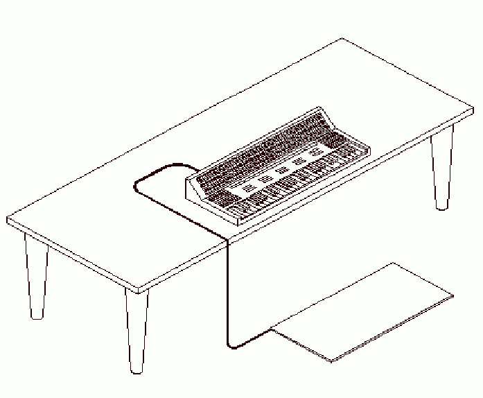
For this design we decided to modify a child size CASIOTONE keyboard. The modifications we designed were: a pressure floor pad switch, an antibang device, extra resistance on the volume control to reduce the overall volume, bilateral logic circuits added to the keyboard circuits, a LED visual display, resembling a graphic equilizer, and an enlarged case to contain the extra circuitry.

The floor pad was to be placed in front of the keyboard, where anyone who wished to operate it would stand or sit. The floor pad was little more than a switch that activated a relay circuit which tuned the power supply on when someone was standing on the floor pad.

The anti bang device was a series of spring actuated switches placed underneath the keys that were designed to close when the force applied to the keys exceeded 6 lbs. The switches were connected to a relay circuit that shut off power to the keyboard, and only reactivated when the teach pushed a button on the back of the unit.

The bilateral logic was the most difficult part. Our design team decided that in order to determine if the child was using both hands, we would color code the keys. In order for the keyboard to work, the child would have to press a two keys of the same color in different colored sections of the keyboard. In order to determine if a key was being pressed, we built a four continuity detector circuits. All the switches under a set of same colored keys were connected to one of the circuits. The four circuits fed into a set of logic gates to determine if conditions for operation were met. If conditions were met, the gate array would activate a relay, providing power for the sound and the lights to work.

The LED (light emiting diode) display resembled a graphic equialiser. When a key in one of the four quadrants was pressed, a set of LEDs above the quadrent would light up, from bottom to top. The circuit used to do this was based on a divide by n timer.


drawing of complete BLAT device